
ME357 FINAL PROJECT
BLACK + DECKER LI2000 DECONSTRUCTION
Day to day activities require little to no knowledge as to how something actually functions. It is curiosity and inquisition that accounts for one to ask, “Why does this work the way it does?” This, in turn, leads to a million other questions: What material is it made out of? What does this part do, and could this function without it? The list goes on. The majority of products are manufactured in a way to not show its inner working mechanisms. To better understand how things work, the best approach is to carefully disassemble the product at hand, and examine the parts housed within and see how every piece works together.
This webpage showcases my final project for ME357: Introduction to Computer Aided Design (CAD). This project displays the utilization of my skills in PTC’s Creo and how I apply CAD to modeling, assembling, and understanding the mechanisms of an operational product.


DISASSEMBLY
Above is a product structure showing the breakdown of the drill, which can best be seen in the picture that follows.
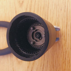
Once the screws and plastic casing is removed, the batter and handle will detach from the motor. The U-pin keeps the motor and gearbox together. Once removed the separation of motor and chuck reveals what pieces remain. These parts include the motor, washer, the ring gear, 6 planetary gears, 1 removable and 1 semi-fixed planetary carrier, and 1 sun gear.
The parts of the gearbox include the planetary carriers, planetary, pinion gears, the ring gear, and the sun gear, all of which make up an epicyclic gear train.
The number of teeth for the planetary, ring, and sun gears are personally counted for, whereas the number of teeth for the planetary carrier is a theoretical number found by the formula: NPC = NR + NS. When modeling the gears on Creo, the simplified approach is to model each gear as its most rudimentary shape as opposed to extruding or pattering the teeth. So, rather than modeling each gear with the correct number of teeth, each gear is modeled omitting teeth extrusions and dimensioned using the pitch diameter.
The reason for this, is that pitch diameters are calculated relating to the correct number of teeth and relating to the other gears. Below is my handwritten work and formulas used to calculate the components of the gears that will then allow me to accurately model and assemble the gearbox on Creo.


EPICYCLIC GEAR TRAIN
Black + Decker Li2000 Gear Box
As stated previously, this particular gearbox is an example of an epicyclic gear train. There are a few advantages in using this setup, including it being compact, having no axial thrust, and being of coaxial shafts. All are plausible reasons as to why companies like and including Black + Decker choose to utilize this type of gear train. Coaxial shafts mean that both the driveshaft and output shaft are on the same axis of rotation. Axial thrusts are notoriously associated with helical gears in that the force that they produce leads to an axial thrust, which would then require a thrust bearing. This drill — handheld and portable — not only needs to be compact itself but needs its components to be equally compact as well. This is why incorporating an epicyclic gear train is most sensible.


Above is an animated mechanism video that does not reflect the B+D Li2000 gearbox but is a similar representation to how it functions. This video is of a 2-stage, epicyclic gear train with 4 planetary gears each, a 4-peg, square planetary carrier, where the shaft and ring gears are held stationary. This video is taken from my ME357 HW11.

THE MECHANISMS OF THE DRILL
Designed with Intent
When it comes to design(s) for manufacturing and assembling (DFMA), companies pay special attention to mistake-proofing. With this drill model, in particular, Black + Decker did just that and here are three instances:
Gear-Shaped Cuts for the Rotating Pin
The rotating pin sits and functions properly in the plastic casing and handle due to the gear-shaped mold and cut that is allocated for these three parts.
Slit for the U-Pin to be Held In Place
Where the motor and gearbox connect, there are 2 sets of equidistant-holes located on opposite sides. In which, a U-shaped pin is inserted and allows for the gearbox to be locked with the motor. While the pin can be inserted on either side and extends throughout both ends, it is properly fitted on the side where there is a minor slit. Said slit locks the U pin in place and properly interlocks the two parts together.
Particular Mold and Indentations for the Motor to Gearbox Connection
The gearbox and motor are designed in such a way that the two pieces interlock neatly and in a particular way due to the indentations and extrusions of each part. In turn, they fit together like two puzzle pieces.


THE ROTATING PIN
This rotating pin allows the screwdriver's handle to pivot. This handheld drill can be adjusted to 180º or just shy of 90º. The video below demonstrates how the pivot button works. When the user presses down on the button, the spring compresses, allowing the user to adjust the angle of the drill handle. Pushing down on the button allows for the extrusions of the orange plastic casing to act as "sliders" and then allows for the handle to pivot.

AUTOMATIC VERSUS MANUAL MODE
The chuck of the drill can switch to one of either two modes: manual or automatic. The symbol for manual use is a hand holding the drill, whereas automatic mode uses a symbol somewhat resembling a lightning bolt. Shown in the video below, the drill can switch into manual mode by moving up a white gear into a position so that it locks with the second planetary carrier. In automatic mode, the white gear is lowered so that the planetary carrier can rotate with the rest of the epicyclic gear train.

FORWARD/REVERSE SWITCH
This drill utilizes a double pole double throw switch (DPDT). A DPDT has 4 outputs and 2 inputs each of which has 2 corresponding outputs that it can connect to. This allows it to reroute the circuit into 2 different modes of operation, in this case, forward or reverse.


TO SUM UP
Personally, I find this drill to be more simplified than others. That being said, after disassembling it multiple times, I realized how well thought out every part is to the drill as a whole. I learned how the automatic and manual "switch" operates and found that to be interesting how a gear — separate than that of the gear train — is inserted or removed to restrict the carrier's movement, in turn, restricting all movement together.